
The rack as it stands, not as it was last documented.
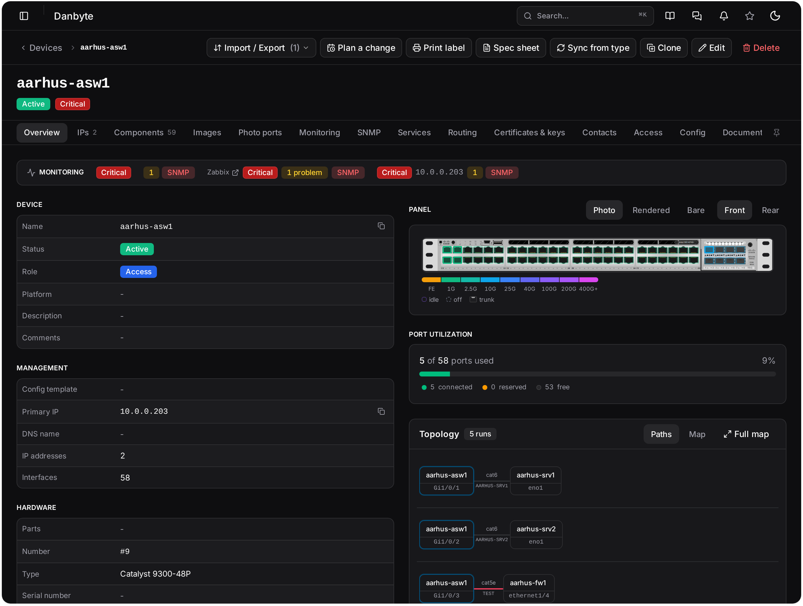
A device knows its type, so Danbyte draws its real faceplate. Cabled ports take their speed tier, free ones are outlined, and a polled port carries a live dot. The elevation is the inventory, drawn.
Racks in three ways
Names for the fastest read, Images for the real photographs, and Render which draws each faceplate as hardware: cabled ports in their speed tier, free outlined, reserved amber, disabled dashed, trunks notched, and a live SNMP dot where the port is polled.
Hover a port for the device card including its far end; click a cabled one for its trace. On the rear, a full-depth server shows its rear photo rather than hatching.
DIN-rail cabinets
A cabinet is an enclosure whose gear sits on DIN rails rather than in rack units: a control cabinet with a PLC and industrial switches, a distribution board. Positions are in millimetres, and the server checks every placement against the rail and its neighbours.
Hardware you can actually recognise
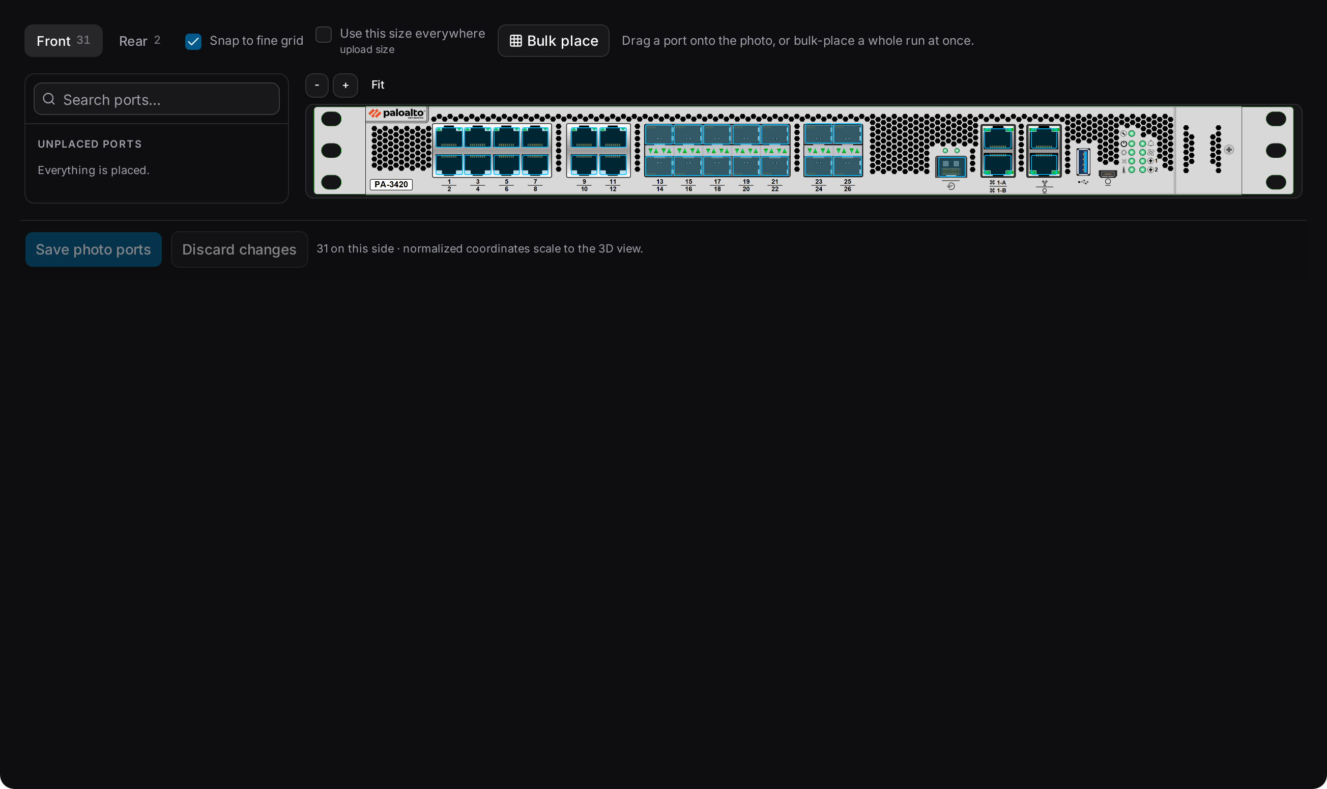
Build a faceplate from a photograph, mark its ports once, and every device of that type draws correctly from then on, in the rack, on the map and in 3D.
Cabling that traces end to end
A trace follows a cable through patch panels to the far end, so a desk outlet resolves to the switch port that serves it. Fibre carries its strands in TIA-598-C order, with LC-duplex and MPO handled properly.
Cables cannot lose an end or join incompatible ports, and a cable tray produces a pull sheet.
Components, and what they are worth
Interfaces, console, power, front and rear ports, and hardware, each with a count and a column picker. Virtual and aggregate interfaces, LAGs and bridges, virtual chassis for stacks, and inventory items for what is inside the box.
Power that adds up
Panels, feeds, PDUs and outlets, with demand measured against supply. A rack can carry its own power budget in watts, and the levels where capacity turns amber and red are yours to set, feeding the racks list, the floor-plan colours and the 3D room from one place.
Questions
- Do I have to draw every faceplate myself?
- No. Device-type bundles carry their photos, ports and calibration, so a library moves between installs complete, and there is an import from the community device-type library.
- Can a rack move site?
- Yes, with every device in it, after a preview that lists what goes, what is cleared and what is blocking the move. It is refused until the blockers are dealt with rather than half-done.
See it with real data.
The live demo is a private instance with a populated estate, yours for thirty minutes. Or install it yourself in a few minutes.